Mars Rover Robotic Arm
|
Capstone Project
June - December 2019 For my capstone project, I worked in a team of 5 mechanical engineering students to design and build a robotic arm for Northeastern's Mars Rover Team. The Rover Team competes in the annual University Rover Challenge hosted by the Mars Society. For the competition, the arm must be remote controlled and be able to pick up and lift 5 kg, flip switches, type on a keyboard, and loosen a screw with a hex key. Additionally, the Rover Team mandated that the arm must weigh less than 10 kg and cost less than $4,000. |
|
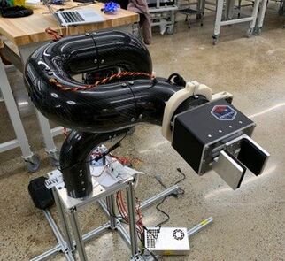
Servo and Planetary Gearbox Joint Design
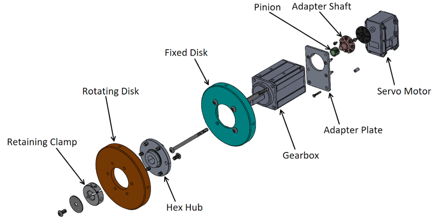
Exploded and labeled comprehensive joint design
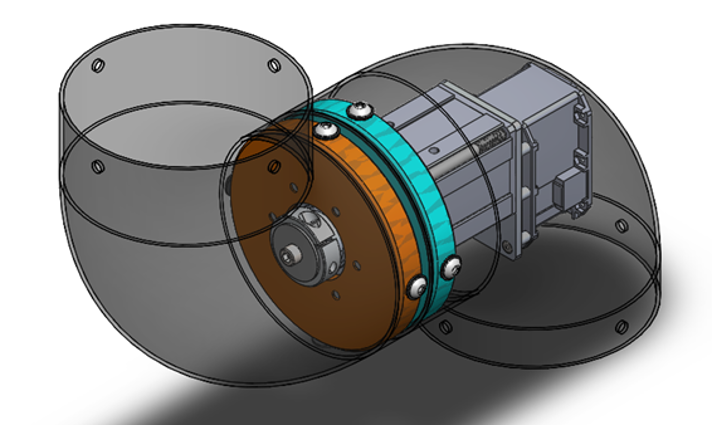
Fully assembled joint in transparent carbon fiber housings
|
Problem: One of the major efforts for the arm was to design the actuators that would pitch, roll, and yaw the 5 joints. The arm that the Rover Team used for last year's competition used custom worm gearboxes that were not strong enough, were hard to control, and had significant backlash.
Action: I led the effort to redesign the actuators. Instead of using worm gears or bevel gears to transmit torque from one straight housing to another, I proposed that we put straight actuators in angled housings. This allowed the input and output torques of the actuators to be coaxial, minimizing mechanical inefficiencies. The joints ended up using Dynamixel servo motors and AndyMark planetary gearboxes to drive multiple custom components housed within the carbon fiber body of the arm. I designed all of the custom parts in the joints and performed hand calculations and SolidWorks FEA to ensure that the structural components and bolt circles would survive infinite life with appropriate safety factors. Result: The joints worked very well, allowing precise, smooth motion, even at the maximum loading conditions. The planetary gearboxes allowed us to get a very high gear ratio in a compact package for a reasonable price, and the servo motors that we used to drive the gearboxes had a built-in absolute encoder that allowed the Rover controls team to track the exact position of each joint at all times. |
|
|
|
|
Here are videos of our finished prototype completing three of the tasks required by the University Rover Challenge. From left to right, the videos are of the arm lifting a 5 kg object, flipping a switch on a service board, and typing out the word "MARS" on a mechanical keyboard.
Hydroid
|
Mechanical Engineering Co-op
January - June 2019 I worked at Hydroid for my third and final co-op. I was a member of the research and development team where I worked on increasing vehicle performance, reliability, and safety while optimizing designs to lower cost and aid in ease of assembly. The two main autonomous underwater vehicles that I worked on were the next generation REMUS 100 and the REMUS M3V. Due to the classified nature of the work, I cannot publicly share specific technical information, but I can provide general information regarding a few of the vehicles and projects I worked on. |
|
REMUS M3V Thruster Redesign
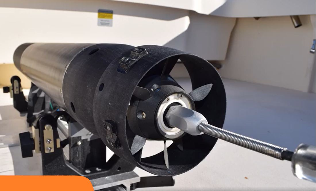
View of original prototype thruster installed in an M3V. My redesign looks similar from the outside, but for proprietary reasons I cannot publicly share photos of mine.
|
Problem: The counter-rotating propeller thruster on the M3V was originally designed with some hobbyist electric motors and crudely designed housings to build a prototype. While this design was a good conceptual starting place, it was not designed with proper consideration for precision rotary motion and was easily hindered by corrosion. I was tasked with redesigning the thruster to accommodate bigger, industrial motors without increasing the overall envelope of the assembly, all while increasing thrust performance and reliability.
Action: I successfully redesigned the thruster to accommodate the new electric motors without increasing the overall envelope. After the redesign, I created production-quality part and assembly drawings with emphasis on proper geometric tolerances and appropriate clearances to allow smooth, precise rotary motion. Result: During my last week at Hydroid, the parts were received, and I was able to build two full thruster assemblies. By spinning the assemblies by hand, I could feel a vast improvement in the mechanical functionality between the old prototype and my redesign. Unfortunately, due to some electrical defects with the motors, the assembly was not functional, and motors had to be sent back out to be rewound and repotted, so I never got to see the thruster in use on a vehicle. That said, I continue to be in touch with some of my former colleagues, and expect to have quantified thrust performance results soon. |
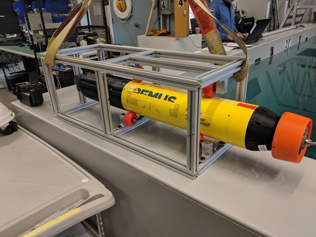
REMUS M3V Roll Fixture
|
Problem: One of the functional requirements of M3V is that the vehicle has to be able to spin and hold any angle about its center axis. This is done by spinning the counter-rotating propellers at different speeds, using their differences in angular momentum to spin the vehicle. The controls team tasked me with designing a fixture that would restrain the vehicle in all directions except rotation about its center axis, allowing it to spin freely in place so they could characterize the roll dynamics based on various input changes.
Action: I decided to make a cage fixture to retain the vehicle. The frame of the cage was made of 80-20 aluminum extrusion. To axially retain the vehicle, I attached a 3D printed plastic pyramid to the front of the cage. As the vehicle was propelled, it would drive itself into the point of this pyramid, stopping it from moving forward while providing a negligible resisting torque. To allow the vehicle to spin while retaining it vertically and laterally, I used three sets of rollers that contacted the vehicle 120° from each other around the circumference of the hull. These rollers had to be slick, firm, non-corroding, and non-abrasive. Although rather unconventional, I decided to use plastic skateboard wheels and ceramic bearings for these rollers. Result: The fixture was very successful, and was used extensively by the company to test M3V's roll dynamics. The skateboard wheels worked perfectly as rollers, and the slots of the 80-20 extrusion allowed the positions of the skateboard wheel mounts to be fine-tuned. Because of this, the wheels were always able to provide the perfect amount of contact with the hull of the vehicle, causing the vehicle to essentially float between the wheels without any extra movement. Although I will admit that it's not an especially complex design, I was proud of the simplicity and ingenuity that led to a very useful tool. Often times when employees would see it for the first time, they would stop and take a look, amused and impressed by the use of something as novel as skateboard wheels in a great fixture. |
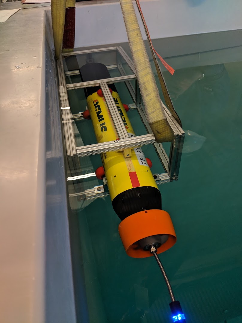
My 80-20 fixture being used to test a prototype M3V
|
Rethink Robotics
|
Mechanical and Quality Engineering Co-op
January - June 2018 I worked at Rethink Robotics for my second co-op. I worked primarily on designing and manufacturing internal test fixtures and quality assurance for the Sawyer Collaborative Robot. |
|
High-Speed Lifetime and Design Verification Toggle Tester
Final SolidWorks assembly of tester
Real-time video of two high-speed tests being performed on the testers
|
Problem: I was tasked with designing a fixture to perform high-speed testing on a redesigned mechanical toggle within Sawyer. These tests were necessary to analyze the current and new designs' lifetimes to ensure that the new design was as durable as the current design. The current method of lifetime testing was to install the toggle in a spare robot and actuate it as if it were in the field - a process that could take up to a year. I was tasked with accelerating the lifetime testing to a more reasonable time period.
Action: I designed, machined, built, wired, and programmed two identical fixtures that used an electric motor to spin a mechanical linkage, which actuated a flipper, which in turn actuated the toggle. I used an Arduino and a laser sensor to track cycle counts and to report and display a cycle count and toggle rate every 10 cycles. Once the laser sensor determined the toggle had failed, the Arduino would slow the motor to a stop and display the cycles to failure on a computer screen. Result: The design was very successful, and the fixtures were used extensively in my time at Rethink. I was able to reach a toggle rate of almost 7 Hz, slashing full lifetime testing of any toggle from 360 days to 10. Between the two fixtures, I tested 10 different toggle designs and was able to isolate the best design, which was rolled into production months earlier than anticipated. |
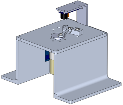
Desktop Actuator Test Fixture
|
Problem: I was tasked with designing a diagnostic fixture to run actuators using simple, intuitive controls. Whenever we had faulty actuators shipped back to us, we had to install them in a spare robot to test them ourselves. This was a long and laborious task because of the complexities of the robot, and a simple desk fixture would save lots of time, allowing us to quickly diagnose mechanical problems.
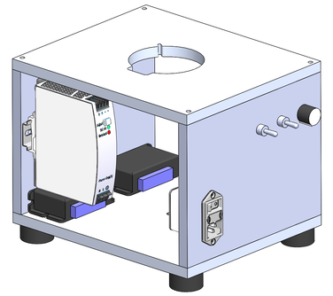
Action: I designed a fixture that used a power supply to power two motor controllers, a DPDT switch to select which motor controller was in use (based on the size of the actuator being tested), a DPST switch to control rotation direction of the actuators, and a dual-gang potentiometer to control rotational speed. I designed and created production drawings for a desktop aluminum housing to hold all of the electronics and interchangeable top plates for each actuator size. Result: I completed the design and assembly of the wiring for the fixture. This allowed me to install and hold any of the three sizes of actuators and control its speed and direction. Although I completed the designs and drawings for the housing, I unfortunately did not have enough time to machine and assemble it before the end of my co-op. However, the design showed lots of promise, and the fixture was approved for internal diagnostic use upon completion. The fixture was expected to cut diagnostic time from 4 hours to 15 minutes. |
SolidWorks assembly of tester
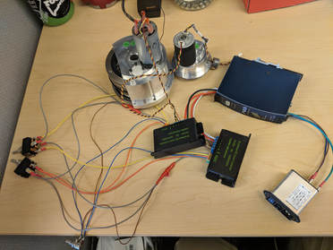
Wired controls and actuators for tester
|
Customer Catalog Models
|
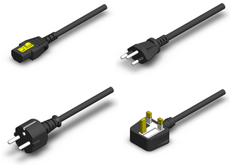
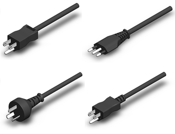
Problem: The current customer catalog was outdated both in terms of design and content. For the new catalog, we wanted to transition from photographs of real parts to pictures of SolidWorks models. I was tasked with creating detailed models for many parts that didn't have SolidWorks files in our database, and creating exploded views of assemblies that could be ballooned for individual part callouts.
Action: I modeled many parts, primarily various power cord plugs, based on partial technical drawings and photographs of real parts. I also created exploded views of gripper attachment kits and replacement hardware kits, working with the graphic design team to ensure that I captured the view they wanted. Result: By the time I left Rethink, the part catalog was still in an internal draft stage, but the plan was to release the document to current and potential customers as a more organized way to view and order replacement and specialty parts. |
QinetiQ - North America
|
Mechanical Engineering Co-op - Maritime Division
January - June 2017 I worked at QinetiQ - North America for my first co-op. I worked primarily on creating and updating production part and assembly drawings and BOMs in SolidWorks for the EMALS and AAG aboard CVN 79, the USS John F. Kennedy. I also managed a fastener replacement and standardization process within the 14-person mechanical engineering department and wrote deviations and engineering change orders. Due to the highly proprietary nature of the work, I cannot provide any public work examples, but I can provide more details of the work in person. |

|
Picnic Table Business Owner
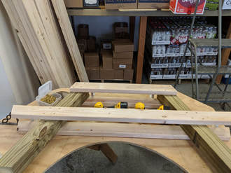
Tabletop jig that I use to build the leg assemblies
|
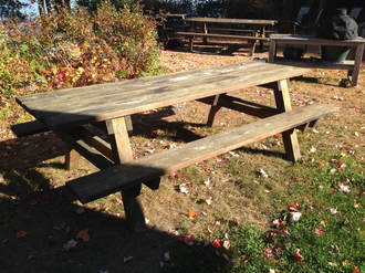
Self-employed
2010 - 2018 When I was 13, a town representative asked to buy a couple of picnic tables from my dad to put in a town park. My dad, instead of building them himself, decided to teach me how to build them, and it evolved into a full-blown business. I started by building two for the town but ended up taking a couple more orders for drive-by tourists. After five or six additional orders, I decided to build up an inventory and make a business out of it. That first summer, I sold 108 picnic tables. The design for the tables has been passed down through the family for many generations, so for that I can't take credit, but they are designed to maximize stability, sturdiness, comfort, and longevity. Since that first summer, I have built and sold almost 350 tables for summer camps, restaurants, parks, seasonal tourists, and locals. Since I picked up more hours at my parents’ business, I have built fewer and fewer, and don't keep a surplus any more. That said, I’ve become known within the local area for the best tables around, and still take orders every summer from people looking for the highest quality picnic table. |
